BOULDEN SOLVES BENEFIELD SOLUTION PUMP PROBLEM
Broken Shaft in Benefield Solution Pump
A fertilizer plant in Southeast Asia had problems with their primary Benfield Solution Pump for many years. Every 18-36 months, the shaft would break leading to major machinery damage. A simple solution from Boulden helped save the plant a lot of money and frustration.
Their Benfield Solution pump is a between bearings, 2-stage, axially split pump (API610 Type BB1). The service is Benfield Solution at 105 C (221 F), pumping 969 m3/hr (4266 gpm) at a differential pressure of 36 bar (522 psi). The pump is rated at 1190 kW (1600 hp). This is a big, important pump for the plant and the repeated shaft failures were causing major headaches.
Mystery Problem
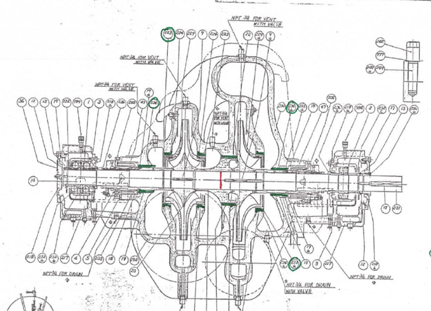
For the plant personnel, the shaft failures were a mystery. The failures presented themselves as a clean 90-degree break underneath the balance sleeve between the stages. Position and direction of break is shown as the red line (show in the figure below and left).
Plant personnel looked for solutions to the problem, but nothing worked. By the time they contacted Boulden, the pump OEM had recommended replacing the pumps at a very high cost. When the plant personnel described the problem to Boulden, we helped the plant identify the failure mode of the shaft. A 90-degree angle shaft break indicates a fatigue failure that occurs over many cycles. In these types of pumps (between bearings), shafts will often break at the center point due to the rotor orbiting within the casing, either like a button on a string or – in the case of a 2-stage pump, the two impellers can orbit like a bicycle crank. A pump running at 1482 rpm will experience billions of fatigue cycles in only a few years.
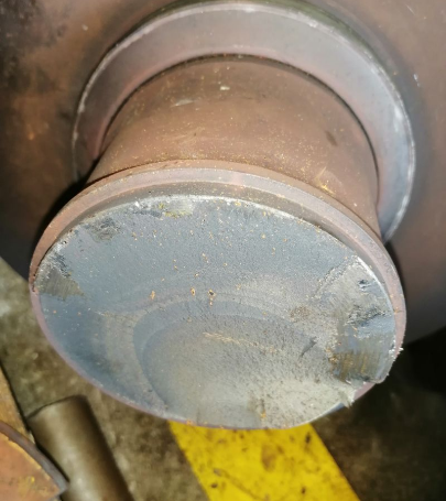
A further tell-tale sign of a fatigue failure is “beach marks” along the break where you can see a crack initiate and then propagate across the shaft (shown in the figure below and right). The plant personnel confirmed that their breakage matched this description.


A Simple Solution
Once the failure mode was identified, Boulden proposed an unexpected approach to the solution: If the plant could reduce the magnitude of deflection during the fatigue cycles, they could push a fatigue failure far into the future.
Boulden proposed using the wear rings, center-stage, and throttle bushings to stabilize the rotor and reduce the magnitude of the fatigue cycles. We retrofitted the stationary wear components with the composite material Vespel® CR-6100 (leaving the original metal wear parts on the rotating elements) and then reduced the running clearance by 50% from an original design value of 0.70—0.80 mm (0.028—0.032”) down to 0.35—0.40 mm (0.014—0.016”). Reducing the clearance at these wear parts increases the Lomakin Effect – the “bearing effect” created by the pump wear rings and bushings.We also added the Boulden PERF-Seal® design to the components. This design significantly increases the damping coefficient of wear parts and helps to further stabilize the rotor.
Boulden worked with a local repair facility to retrofit the wear parts which were then installed at the next pump overhaul. Once the pump was back online, plant personnel noted that it was running very smoothly with low vibration levels. It has now been running for nearly 4 years without issues. At a minimum, the pump life has increased and the plant saved huge capital outlays by not having to replace the pumps.